
JLYPT Manufacturing Case Study
3 mm micro needle.
A demanding machining challenge.
JLYPT recently helped a customer complete a challenging miniature needle project. The part measures approximately 3 mm, with selected features measuring just 0.2–0.3 mm.
Discuss a Similar Part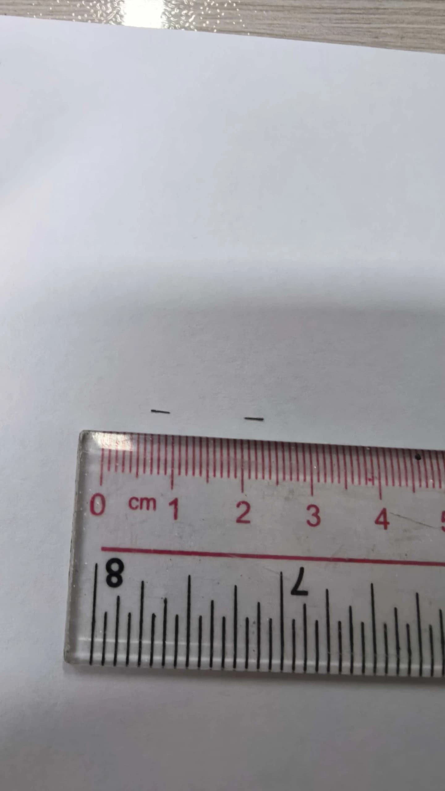
- Part size
- 3 mm
- Selected feature dimensions
- 0.2–0.3 mm
- Customer project status
- Completed
The project brief
The customer needed a miniature needle with sub-millimetre features. JLYPT completed the project and supplied the physical components shown in the photographs below. At this scale, a useful manufacturing discussion starts with the geometry of each feature and the function it must perform.
The 3 mm part size and 0.2–0.3 mm feature dimensions describe geometry. Dimensional tolerances are a separate requirement, defined on the controlled drawing and assessed for each project.
A closer look, with sensitive geometry protected
Show the scale. Protect the design.
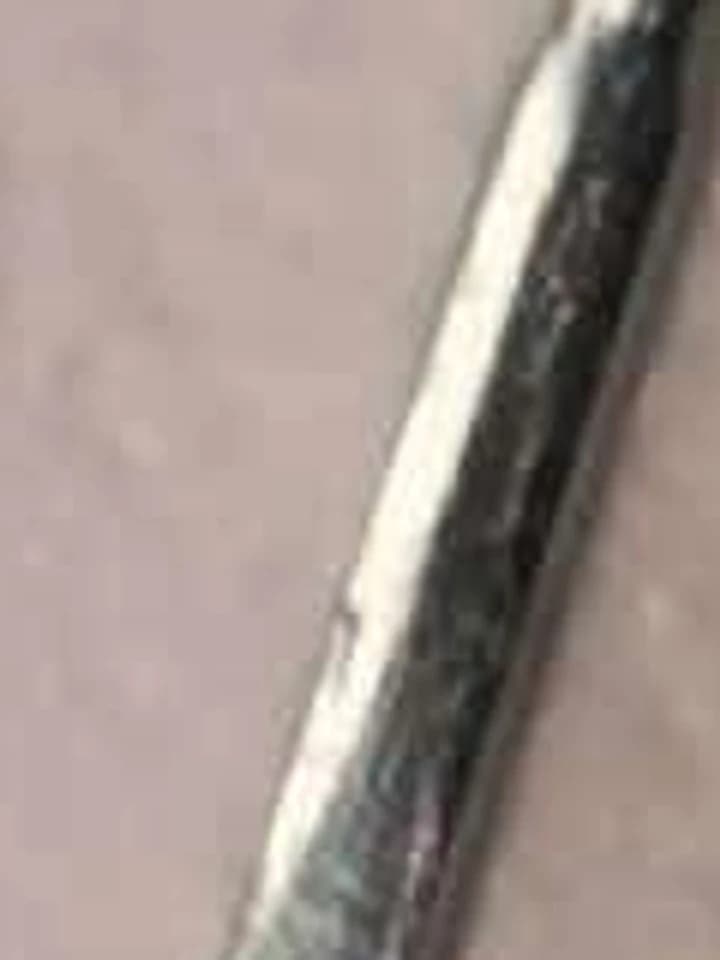
The full ruler photograph shows how small the physical components are. The close-up is limited to one surface area so it does not expose the complete product geometry.
The selected 0.2–0.3 mm feature dimensions describe the project’s scale without identifying their positions on the part. Detailed geometry and functional interfaces remain confidential.
Why miniature features need careful planning
A small overall envelope can contain several different manufacturing problems. For a similar micro machining enquiry, the engineering review should address:
- Feature geometry and support. Slender sections, small transitions and the available holding area affect how a part can be supported during manufacture.
- Edges and handling. Burrs, edge condition and damage during handling deserve explicit requirements when the functional features are only fractions of a millimetre.
- Inspection access. The drawing should identify which features need to be measured, their tolerances and the required evidence. A magnified photograph and a dimensional report serve different purposes.
These are planning considerations for similar miniature parts. The manufacturing route and inspection method should be selected after reviewing the material and drawing.
The outcome
JLYPT completed the customer’s challenging micro needle project. The ruler comparison and selected surface detail make the scale tangible: an approximately 3 mm component with selected features of 0.2–0.3 mm.
Watch the project overview
The video uses actual project photographs and on-screen English text.
Have a miniature part that is difficult to make?
Share your 2D drawing and 3D model, material specification, critical feature dimensions and tolerances, required quantity, edge requirements and inspection expectations. Our team can review the manufacturing challenges and discuss a practical route.